Power instability in laser equipment isn’t just an annoyance—it can bring production to a halt, compromise precision, and shorten component life. Whether you’re working with CO₂, fiber, or solid-state lasers, a systematic approach to diagnosing and repairing power loss or fluctuation will get your system back on track quickly. Below, we break down every step—from initial inspection to final verification—to help you conquer erratic output and restore steady performance.

1. Understand the Symptoms
Before diving into repairs, clearly characterize the problem:
Gradual Power Decline: Output drops slowly over days or weeks.
Sudden Power Drop: A sharp fall in output during a cut or pulse.
Intermittent Fluctuation: Power surges and dips unpredictably.
Startup Inconsistency: Full power only reached after multiple restarts.
Logging these patterns—including when they occur, under what load, and any accompanying error codes—guides your troubleshooting path and avoids wasted effort.
2. Verify the Power Supply
A. Mains and Input Voltage
Measure Incoming Voltage
Use a true-RMS multimeter to confirm your facility’s mains voltage is within ±5% of the laser’s rated input.
Inspect Circuit Protection
Check fuses, breakers, and surge protectors for signs of tripping, corrosion, or heat-related discoloration.
B. Internal Power Modules
DC Bus and High-Voltage Rails
With the system powered on, carefully measure key voltage rails (e.g., +48 V, +5 V, ±12 V) against factory specifications.
Capacitor Health
Look for bulging or leaking electrolytic capacitors on power boards. A capacitance meter can confirm degradation.
Tip: Always follow lock-out/tag-out procedures and discharge high-voltage capacitors before probing.
3. Inspect the Pump Source
In diode-pumped and flashlamp-pumped lasers, the pump module directly drives output power.

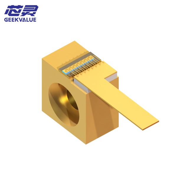
A. Diode Lasers (Fiber & Diode Bar Systems)
Diode Current: Measure forward current; it should match the specified amperage under no-load conditions.
Temperature Control: Verify thermoelectric cooler (TEC) setpoints and actual module temperature. Diode efficiency and lifetime suffer if temperature drifts by more than ±2 °C.
Connector Integrity: Ensure fiber pigtails or diode bar solder joints show no cracks, discoloration, or mechanical stress.
B. Flashlamp Systems (Nd:YAG, Ruby)
Pulse Charging Voltage: Use a high-voltage probe to confirm the capacitor bank charges to the correct voltage before each flash.
Lamp Condition: Discolored or blackened lamp envelopes indicate gas contamination and reduced pumping efficiency.
4. Evaluate Cooling and Thermal Stability
Heat is the silent culprit behind many power issues. Poor cooling can force the system into thermal protection mode, throttling power to prevent damage.
Coolant Flow Rate
For water-cooled lasers, measure flow with a paddle wheel or ultrasonic flowmeter.
Temperature Differential
Record inlet vs. outlet coolant temperatures. A rise greater than the manufacturer’s maximum (often 5–10 °C) signals blocked channels or failing chillers.
Air-Cooled Units
Inspect fans for proper RPM, and clean air filters or heatsinks to restore airflow.
5. Check Beam Path Components
Optical losses—caused by dirty or misaligned optics—can mimic power fluctuation at the output.
Protective Windows & Lenses
Remove and clean with optical-grade solvents; replace if pitted or scratched.
Mirrors & Beam Splitters
Verify alignment with alignment cards or beam viewers; even a 0.1° tilt can reduce throughput by several percent.
Fiber Connectors (Fiber Lasers)
Inspect end-faces under a fiber microscope; re-polish or replace connectors showing damage.
6. Review Control Electronics and Software
Modern lasers rely on feedback loops to regulate output. Software or sensor errors can introduce apparent power instability.
Sensor Calibration
Check photodiode or thermopile readings against an external power meter.
Firmware & Parameter Settings
Ensure PID loop gains and power ramp rates haven’t been inadvertently changed. Revert to known-good configurations if necessary.
Error Logs
Export system logs to identify recurring faults—such as “pump current out of range” or “thermal trip”—and address root causes.
7. Final Testing and Validation
After corrective actions, verify that the system delivers consistent power across its operating envelope:
No-Load Stability: Measure output power at idle to confirm baseline consistency.
Load Testing: Run representative cutting or welding jobs while logging power in real time. Look for deviations beyond ±2% of nominal power.
Long-Duration Burn: Operate the laser at high power for several hours to ensure no thermal drift or component fatigue.
Document all before-and-after measurements alongside repaired components or settings changed. This record not only proves the fix but also aids future troubleshooting.

8. Proactive Measures to Prevent Recurrence
Scheduled Electrical Audits: Quarterly checks of mains quality and internal power rails.
Spare Part Readiness: Keep critical items—diode modules, flashlamps, capacitors, cooling filters—on the shelf.
آپریٹر کی تربیت: Teach staff to spot early warning signs, like unusual fan noise or slight power dips, before they escalate.
Environmental Controls: Maintain stable temperature and humidity in the laser enclosure to reduce stress on electronics and optics.
By following this structured diagnostic and repair workflow, you’ll swiftly identify and resolve power loss or fluctuation issues in any laser system. Consistent documentation, combined with scheduled preventive checks, transforms reactive repairs into proactive maintenance—keeping your lasers humming at full power with minimal downtime.


