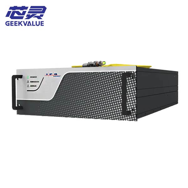
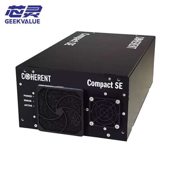
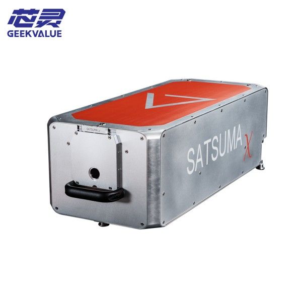
IPG Photonics is a leading global manufacturer of high-power fiber lasers. Its products are known for their high efficiency, long life and stability, and are widely used in industrial processing, military, medical and scientific research. IPG lasers are mainly divided into three categories: continuous wave (CW) lasers, quasi-continuous wave (QCW) lasers and pulsed lasers, with power ranging from a few watts to tens of kilowatts.
A typical IPG laser consists of the following core modules:
1. Pump source module: including laser diode array
2. Fiber resonator: ytterbium-doped fiber and Bragg grating
3. Power supply and control system: precision power supply and monitoring circuit
4. Cooling system: liquid cooling or air cooling device
5. Beam transmission system: output fiber and collimator
2. Common fault diagnosis methods
2.1 Fault code analysis
IPG lasers are equipped with a complete self-diagnosis system, and the corresponding error code will be displayed when an abnormality occurs. Common fault codes include:
• E101: Cooling system failure
• E201: Power module abnormality
• E301: Optical system alarm
• E401: Control system communication error
• E501: Safety interlock triggered
2.2 Performance parameter monitoring
The following key parameters should be recorded before maintenance:
1. Deviation of output power from the set value
2. Change in beam quality (M² factor)
3. Coolant temperature and flow
4. Current/voltage fluctuations
5. Temperature distribution of each module
2.3 Use of diagnostic tools
• IPG dedicated diagnostic software: IPG Service Tool
•Fiber end face detector: Check the output end face for contamination or damage
•Spectrum analyzer: Detect output wavelength stability
•Thermal imager: Locate abnormal hot spots
III. Core module maintenance technology
3.1 Optical system maintenance
Common problems:
•Output power reduction
•Beam quality deteriorates
•Fiber end face contamination or damage
Maintenance steps:
1. End face cleaning:
o Use a dedicated fiber cleaning rod and reagent (isopropyl alcohol)
o Follow the "wet-dry" two-step method
o Keep the cleaning angle at 30-45 degrees
2. Fiber replacement:
Operation process
1. Turn off the power and wait for the capacitor to discharge
2. Mark the original position of the fiber
3. Loosen the fiber clamp
4. Remove the damaged fiber (avoid bending)
5. Install the new fiber (keep the natural bend)
6. Accurately align and fix
7. Power gradual recovery test
3. Collimator adjustment:
o Use the red light indicator to assist in alignment
o Each fine-tuning screw should not exceed 1/8 turn
o Real-time monitoring of output power changes


